Estimación del tiempo de cebado de una bomba autocebante: Guía de cálculo práctica
A manufacturer’s spec sheet stating a pump “primes in under 3 minutes” is a measurement, not a promise — it was recorded at one specific suction lift, one specific suction line diameter, and one specific suction line length. Change any of those three variables on your actual job site, and the real priming time moves away from that published figure in a way you can estimate, but not by simply assuming the printed number applies everywhere. This works through the calculation.
On This Page
- Why “Primes in Under 3 Minutes” Isn’t a Number You Can Apply Directly
- The Governing Relationship: Air Volume vs. Evacuation Rate
- Step 1: Calculating Total Air Volume in the Suction Line
- Step 2: Scaling From Manufacturer Reference Conditions
- Step 3: A Worked Example
- When This Estimation Method Breaks Down
- Quick Reference Table
- Frequently Asked Questions
Why “Primes in Under 3 Minutes” Isn’t a Number You Can Apply Directly
A published priming time is a test result, tied to the specific reference conditions the test was run under — typically a defined suction lift, a suction hose matching the pump’s rated inlet diameter, and a fixed hose length representative of a “typical” setup rather than your specific one. Change the suction lift, swap to a longer or larger-diameter hose, or run the unit at a different engine speed than the test condition, and the real priming time shifts away from the published figure — sometimes considerably. This matters because a self-priming pump’s priming time, unlike its flow-head performance curve, isn’t governed by a single physical law with published coefficients; it’s a system-level outcome of air volume, suction lift, and internal chamber efficiency that manufacturers characterize through testing rather than through a formula they publish alongside it. What follows is a method for estimating how that published figure should be expected to change under your actual field conditions.
The Governing Relationship: Air Volume vs. Evacuation Rate
A vacuum-assisted priming system has a dedicated vacuum pump with a published air displacement rate — a genuine specification in CFM or liters per minute that a first-principles calculation can be built around directly. A self-priming pump has no equivalent published number, because its “evacuation rate” isn’t a separate component spec — it emerges from impeller speed, retained water volume, and separation chamber geometry working together, none of which are published as a standalone air-handling figure. This is why the estimation method below doesn’t derive priming time from first principles; instead, it uses the manufacturer’s own published reference result as a calibration point and scales it proportionally against the two variables that most directly govern how much work the system has to do: the total air volume that needs evacuating, and the suction lift atmospheric pressure has to overcome to replace that air with water.
Step 1: Calculating Total Air Volume in the Suction Line
The suction line’s internal volume — treated as a simple cylinder — approximates the total air volume the priming cycle needs to remove before the line floods completely:
Where V is internal volume, d is the suction line’s internal diameter, and L is its total length. This is deliberately a simplification — it ignores minor volume contributions from fittings and the pump casing’s own internal passages — but the suction hose or pipe run is by far the largest air volume in the system on most field setups, making it the dominant term worth calculating explicitly.
Step 2: Scaling From Manufacturer Reference Conditions
With the reference volume (Vref, from the manufacturer’s stated test hose diameter and length) and your actual field volume (Vactual) both calculated using the formula above, and the reference suction lift (Liftref) and your actual suction lift (Liftactual) both known, the estimated priming time scales proportionally against both ratios:
This treats the pump’s underlying air-evacuation capability as roughly constant between the reference test and your field setup — a reasonable assumption since it’s the same pump model, same impeller speed, and same separation chamber design in both cases — while directly accounting for the two variables most likely to differ: how much air there is to remove, and how much atmospheric pressure “work” is needed to replace it with water at your actual lift.
Step 3: A Worked Example
Worked Calculation
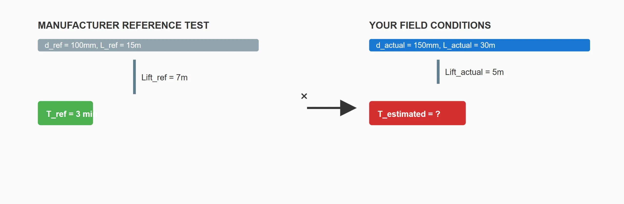
Manufacturer reference condition: primes in 3 minutes at 7m suction lift, using a 100mm diameter, 15m long suction hose.
Reference volume: Vref = (π ÷ 4) × 0.1² × 15 = 0.1178 m³
Your field condition: 5m suction lift, using a 150mm diameter, 30m long suction hose (a larger, longer run than the reference test, but a shallower lift).
Field volume: Vactual = (π ÷ 4) × 0.15² × 30 = 0.5301 m³
Volume ratio: 0.5301 ÷ 0.1178 ≈ 4.50
Lift ratio: 5 ÷ 7 ≈ 0.714
Estimated priming time: 3 min × 4.50 × 0.714 ≈ 9.6 minutes
Despite a shallower lift than the reference test — which on its own would suggest faster priming — the larger diameter and longer hose contain more than four times the air volume of the reference setup, and that volume increase dominates the result. This is the practical value of running the calculation rather than assuming a shallower lift automatically means a faster prime: the two variables can pull in opposite directions, and only the arithmetic tells you which one wins.
When This Estimation Method Breaks Down
The calculation above assumes the pump’s underlying air-evacuation capability is unchanged from the reference test — an assumption that stops holding in several real-world conditions:
- Check valve or foot valve wear — a valve that no longer seals fully lets retained casing water drain back between cycles, extending real priming time well beyond the estimate regardless of the volume and lift math.
- Separation chamber wear or fouling — sediment buildup or erosion in the chamber reduces how completely it separates air from water per cycle, which the volume-ratio calculation has no way to account for.
- Reduced engine speed — if the unit is running at lower RPM than the manufacturer’s test condition (throttled down, or a variable-speed unit not at full speed), the evacuation rate itself is lower than the reference case, and the estimate will understate actual priming time.
- Altitude and ambient conditions — atmospheric pressure, the force actually pushing water up the suction line, decreases with elevation; at meaningfully higher altitude than the reference test, priming will generally take longer than this method predicts.
On a Self-Priming Diesel Trash Pump, such as our trailer-mounted solids-handling configuration, entrained sediment in the retained water adds a further variable this calculation doesn’t model at all. For time-critical or safety-critical deployments, treat this method as a planning-stage estimate to compare configurations against each other, not as a substitute for manufacturer-verified performance data on the specific unit and condition in question.
Quick Reference Table
Air volume for common suction line diameter and length combinations, useful for quickly estimating the volume ratio without recalculating from scratch each time:
| Diameter | 10m Length | 20m Length | 30m Length |
|---|---|---|---|
| 100mm | 0.0785 m³ | 0.1571 m³ | 0.2356 m³ |
| 150mm | 0.1767 m³ | 0.3534 m³ | 0.5301 m³ |
| 200mm | 0.3142 m³ | 0.6283 m³ | 0.9425 m³ |
Divide any cell by your manufacturer’s reference volume to get the volume ratio directly, then multiply by your lift ratio and the published reference time to reach an estimate.
Frequently Asked Questions
Q: Why isn’t there a single universal formula for self-priming pump priming time, the way there is for flow and head?
A: Flow and head follow well-established hydraulic relationships with published coefficients. Priming time depends on internal separation chamber efficiency and recirculation dynamics that are specific to each pump’s casing geometry and aren’t published as a standalone specification — which is why estimation has to work from a manufacturer’s tested reference point rather than a general physical formula.
Q: Does a larger-diameter suction hose always mean slower priming?
A: Not necessarily on its own — a larger diameter increases air volume to evacuate (slower priming, all else equal) but may also reduce friction losses that affect other aspects of performance. For priming time specifically, the volume increase is what matters, and the worked example above shows it can dominate even when lift is more favorable.
Q: How much does altitude actually affect priming time estimates?
A: Atmospheric pressure — the force replacing evacuated air with water — decreases with elevation, meaning less “push” is available to raise the water column at a given lift. This calculation method doesn’t include an altitude correction term, so estimates at meaningfully high elevation should be treated as optimistic relative to real performance.
Q: Can this same estimation method be applied to a vacuum-assisted pump instead?
A: Not directly — a vacuum-assisted system’s air evacuation rate is a published, fixed specification of its separate vacuum pump, which allows a more direct first-principles time calculation (volume divided by rated evacuation rate) rather than the proportional-scaling method used here, which exists specifically because self-priming pumps lack that standalone published rate.
For verified priming performance data on a specific model and site condition, contact the CANNASPRING engineering team rather than relying on an estimate alone for critical applications.