How a Self Priming Pump Works
This covers the internal mechanism only — what physically happens inside a self-priming pump between a dry shutdown and stable, fully primed flow. It assumes you already know what a self-priming pump is and have decided to use one; for those questions, see our separate What Is a Self Priming Pump? and Why Choose a Self Priming Pump? guides. What follows is the step-by-step physical process, the variables that govern how long it takes, and what each specific failure mode reveals about the mechanism itself.
On This Page
- The Starting Condition: A Dry Casing After Shutdown
- Step 1: Impeller Rotation Creates an Air-Water Mixture
- Step 2: Air-Water Separation Inside the Chamber
- Step 3: Recirculation Draws the Suction Line Down
- Step 4: Reaching Full Prime and Stable Flow
- What Determines Priming Time
- What Happens When Self-Priming Fails
- Frequently Asked Questions
The Starting Condition: A Dry Casing After Shutdown
When a self-priming pump shuts down, gravity drains most of the liquid out of the volute and suction line, but not all of it. The casing’s internal geometry positions a reservoir volume below the impeller’s shaft centerline — physically lower than any drain path back toward the suction connection — so this portion of liquid has nowhere to go and stays trapped in the casing. At the suction side, a foot or check valve at the inlet closes as flow stops, sealing the suction line at whatever air pressure existed in it at shutdown — normally atmospheric. The result is a specific starting condition every priming cycle begins from: a closed volume of retained liquid sitting in the casing below shaft level, and a suction line that is now sealed and filled with air rather than water. Nothing about the priming process that follows works without both of these conditions being true at startup.
Step 1: Impeller Rotation Creates an Air-Water Mixture
At startup, the impeller begins spinning within the retained water pool sitting in the casing. Because the impeller eye sits at or below the surface of that retained water, rotation immediately puts the liquid into high-velocity turbulent motion rather than smooth, laminar circulation — and this turbulence is the mechanically important part. A slowly stirred pool of water wouldn’t pull air in from the suction connection at all; it takes genuinely violent, high-shear turbulence at the impeller to tear air from the connected suction passage and disperse it as fine bubbles throughout the water, producing a churning air-water froth rather than two separate layers of air and liquid. This is why self-priming pumps are specified with a minimum retained water volume and a minimum startup speed — too little turbulence at this stage and the process that follows never gets enough entrained air moving through the system to make progress.
Step 2: Air-Water Separation Inside the Chamber
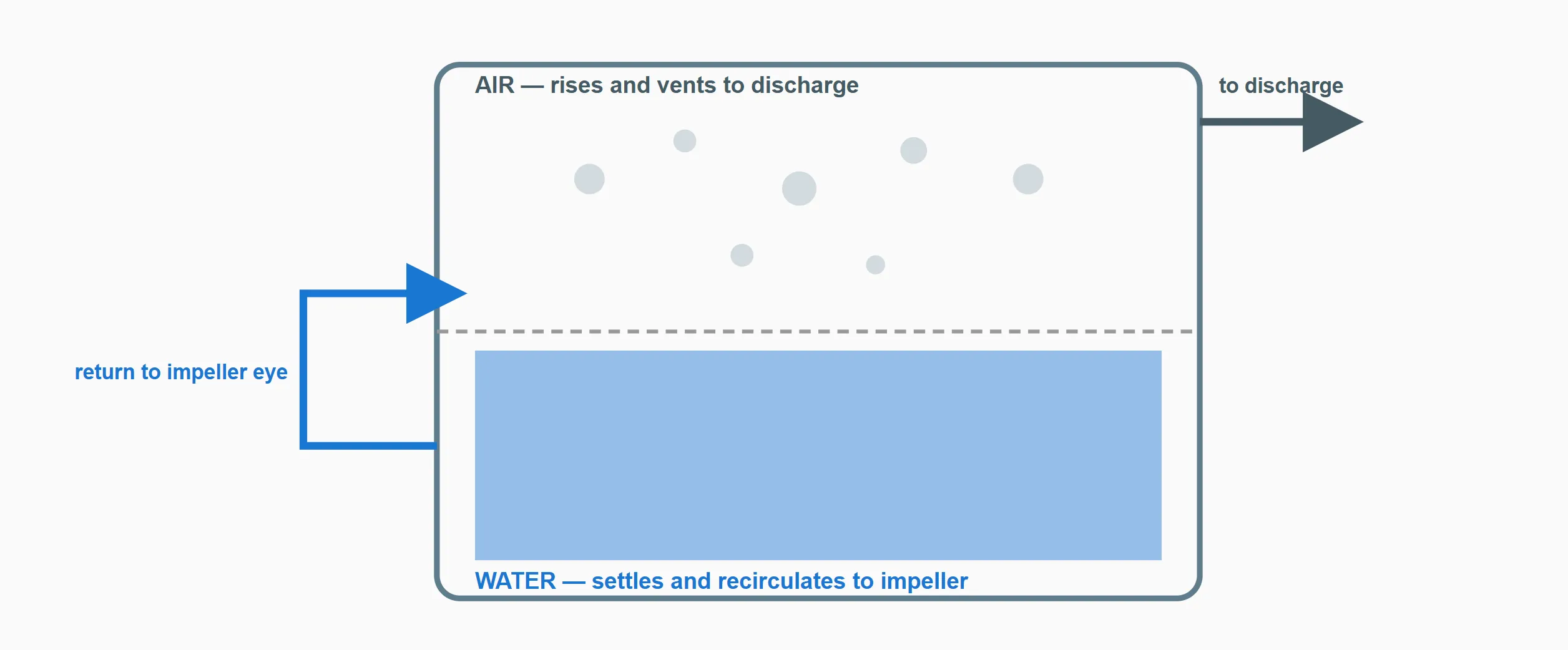
The churned air-water mixture is thrown outward by the impeller into a separation chamber cast into the pump body — a section of the casing specifically shaped to slow the mixture down rather than push it straight through to the discharge port. As velocity drops in this chamber, the turbulence that kept air and water mixed can no longer overcome the large density difference between the two: air, roughly a thousand times less dense than water, rises and collects toward the top of the chamber while water settles toward the bottom, in essentially the same physical process that lets foam separate out of agitated water once it’s left still. The chamber’s internal shape — its volume relative to the casing, and the geometry of the baffle or passage separating its upper and lower sections — determines how completely this separation happens on each single pass; a poorly shaped chamber lets partially-mixed fluid continue toward the discharge without fully separating, which is the direct mechanical reason two self-priming pumps with identical flow and head ratings can reprime at meaningfully different speeds.
Step 3: Recirculation Draws the Suction Line Down
The separated water doesn’t leave the pump — an internal passage routes it back to the impeller eye to be churned again, while the separated air continues onward and vents out through the discharge, where its low density and negligible resistance let it pass easily even against whatever head the discharge line presents. Each time this cycle completes, a small volume of air that used to occupy the suction line has been permanently removed from the system and vented away, while the water that recirculates stays in the pump to repeat the process. This is the mechanical core of “self-priming”: the pump isn’t pulling water up the suction line directly at this stage — it’s removing air from the closed system pump-and-suction-line volume, cycle by cycle, and atmospheric pressure acting on the open water source is what actually pushes replacement water up the suction line to fill the space the removed air used to occupy. Each cycle’s worth of vented air corresponds to a small rise in the water column inside the suction line, which is why priming looks gradual rather than instantaneous — it genuinely is a repeated, incremental process, not a single event.
Step 4: Reaching Full Prime and Stable Flow
The cycle described above repeats until the suction line no longer contains any air pocket for atmospheric pressure to have leverage against — at that point the line is fully flooded, and the impeller is working against a continuous column of liquid rather than a mixture of air and water. Physically, this is the moment the pump’s behavior changes from a low-density, low-resistance mixture that generates negligible real head, to a fully liquid-loaded impeller capable of generating its rated head and flow according to its normal performance curve. The internal recirculation path continues to exist and function throughout normal operation — it doesn’t switch off — but once the suction line is fully flooded there’s no more air arriving from that direction for it to process, and the pump simply behaves as a conventional centrifugal pump moving liquid at whatever flow and head its curve dictates for the connected system.
What Determines Priming Time
Since priming is a repeated, incremental process rather than a single action, the time it takes is governed by how much air has to be removed and how much a single cycle can remove:
| Variable | Effect on Priming Time |
|---|---|
| Suction lift (vertical height) | Greater lift means atmospheric pressure has more work to do pushing each incremental volume of water higher — priming takes longer as lift increases |
| Suction line diameter and length | A larger or longer line simply contains a greater total air volume that has to be evacuated cycle by cycle before the line is fully flooded |
| Retained water volume | Too little leaves insufficient liquid to sustain effective turbulent entrainment; excess beyond the design volume doesn’t meaningfully speed the process further |
| Separation chamber efficiency | A chamber that separates air and water more completely per pass removes more air per cycle, directly reducing the number of cycles — and therefore time — needed to reach full prime |
On solids-handling variants such as a Self-Priming Diesel Trash Pump, such as our trailer-mounted configuration, the separation chamber has to accommodate entrained sediment moving through the same recirculation path alongside air, but the underlying variables governing priming time described above still apply unchanged — solids handling is a separate design consideration layered onto the same core mechanism, not a different priming process.
What Happens When Self-Priming Fails
Tracing common failure modes back through the mechanism above explains why each one specifically prevents priming, rather than just degrading performance generally:
Retained water has leaked or drained away. Without a reservoir of liquid in the casing at startup, the impeller spins in air alone — there’s no water to churn into an air-water mixture in Step 1, so the entire recirculation cycle never begins. This is why a self-priming pump that’s been fully drained cannot reprime unaided; the starting condition the whole mechanism depends on simply isn’t present.
The suction line has an air leak. A loose fitting or a cracked hose lets atmospheric air continuously re-enter the suction line from outside, refilling the very air volume the recirculation cycle is trying to remove. If air comes in from the leak as fast as or faster than the cycle vents it out through the discharge, the net air volume in the line never decreases — the pump can run indefinitely without ever reaching full prime, since the incremental progress described in Step 3 is being continuously undone.
The foot or check valve is stuck open or damaged. This valve’s job is holding the retained casing water and the partially primed suction line in place between duty cycles. If it fails to seal, water that had been drawn up during a previous priming cycle simply drains back down through the open valve by gravity once the pump stops — meaning the next startup begins from a worse position than the last shutdown left it, extending or entirely preventing successful priming on the next attempt.
Frequently Asked Questions
Q: Why does a self-priming pump only remove a small amount of air per cycle instead of clearing the suction line in one pass?
A: Each cycle is limited by how much air the impeller can entrain into the retained water and how completely the separation chamber can then extract that air before the mixture recirculates. Removing the entire suction line’s air volume in one pass would require far more retained water and a vastly larger separation chamber than is practical to build into a compact pump casing — the incremental, repeated-cycle approach is what makes the mechanism fit inside a normal pump housing.
Q: Does the internal recirculation process stop once the pump is fully primed?
A: The recirculation passage remains physically open and functional throughout normal operation, but once the suction line is fully flooded there’s no more entrained air arriving for it to process — so its role becomes functionally irrelevant to normal flow, rather than being mechanically disabled.
Q: Why does a higher suction lift increase priming time specifically, rather than just reducing final flow?
A: Priming time depends on atmospheric pressure pushing replacement water up the suction line each cycle as air is removed. A greater vertical lift means more atmospheric pressure “work” is required to raise each incremental volume of water that same distance, which slows the rate at which the water column climbs — a separate effect from how lift also affects the pump’s final rated flow and head once fully primed.
Q: If the separation chamber is undersized, does the pump fail to prime completely, or does it just prime more slowly?
A: In most cases it primes more slowly rather than failing outright — an undersized or poorly shaped chamber separates air and water less completely per pass, requiring more cycles to remove the same total air volume. In more severe cases, a chamber that cannot separate the mixture adequately at all can let partially-mixed fluid continue toward the discharge indefinitely without net progress, which does functionally prevent priming.
For questions about priming performance on a specific model or application, contact the CANNASPRING engineering team.