Flood Control Pump Working Principle
How Does a Flood Control Pump Work?
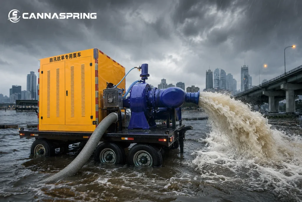
A flood control pump is a type of centrifugal pump designed to move large volumes of water by converting mechanical energy into hydraulic energy. Its working principle is based on centrifugal force and pressure difference generated by a rotating impeller.
When the diesel engine or motor starts, it drives the pump shaft and impeller at high speed. In most trailer mounted pump systems, the rotating impeller creates a low-pressure zone at its center, continuously drawing water into the pump through the suction pipe.
Once inside the impeller, water gains kinetic energy due to centrifugal acceleration. This high-speed flow is then directed into the volute casing, where velocity is gradually converted into pressure energy, enabling the water to be discharged through the outlet.
Basic Working Principle of a Centrifugal Flood Control Pump
The operation of a flood control pump follows the fundamental principles of fluid dynamics, especially Bernoulli’s principle and centrifugal force. The process can be explained as a continuous energy conversion cycle.
Step 1 – Pressure Reduction at the Impeller Eye
As the impeller rotates, fluid near the center is thrown outward, creating a low-pressure region at the impeller eye. This pressure difference allows atmospheric pressure to push water into the suction line.
Step 2 – Fluid Acceleration by Centrifugal Force
Water entering the impeller is accelerated outward along the rotating vanes. During this process, mechanical energy is converted into kinetic energy, increasing the velocity of the fluid.
Step 3 – Energy Conversion in the Volute Casing
The volute casing gradually expands in cross-sectional area, reducing fluid velocity while converting kinetic energy into pressure energy. This pressure buildup is essential for long-distance or high-lift water discharge.
For mobile flood-control and dewatering applications that require higher discharge head or long-distance pumping, a high-head trailer-mounted dewatering pump can be a suitable configuration for efficient water removal.
Step 4 – Continuous Discharge and Flow Maintenance
The pressurized water is discharged through the outlet pipe while new water continuously enters the pump. This creates a stable and uninterrupted flow suitable for flood control pump applications.
Key Components and Their Functions
| Component | Function |
| Diesel Engine / Motor | Provides mechanical power to drive the pump system |
| Pump Shaft | Transfers rotational energy to the impeller |
| Impeller | Converts mechanical energy into fluid kinetic energy |
| Volute Casing | Converts velocity into pressure energy |
| Suction Pipe | Guides water into the pump inlet |
| Discharge Outlet | Releases pressurized water to the drainage system |
Why Centrifugal Pumps Are Suitable for Flood Control
Centrifugal pumps are widely used in flood control systems because they can deliver high flow rates with a relatively simple mechanical structure. Their continuous-flow operation makes them suitable for rapid drainage in emergency situations such as urban flooding, construction site dewatering, and tunnel water removal.
Compared with positive displacement pumps, centrifugal pumps are better suited for handling large volumes of low-viscosity fluids like rainwater and surface runoff.
For flood-control applications that require very high flow at relatively low discharge head, a mixed-flow trailer pump can be a suitable option for moving large volumes of relatively clean water. CannaSpring’s CHWY series is designed for 100–5200 m³/h at 4–20 m head and is intended for clean-water or similar liquid transfer.
Conclusion
The working principle of a flood control pump is based on continuous centrifugal energy conversion. By creating a pressure difference between the suction and discharge sides, the pump enables efficient and continuous water movement, making it a reliable solution for flood control and emergency drainage systems.