
Trailer Mounted Water Pump Anatomy: Component Design and ISO 9906 Performance Tolerances
Two units can carry an identical flow and head rating on their nameplate and still perform completely differently over a five-year service life. The gap comes from what the nameplate doesn’t show: engine emissions tier and duty rating, coupling design, casing and impeller metallurgy, seal type, chassis construction, and fuel system design. This is a component-level look at how a trailer mounted water pump is actually engineered, and which design decisions in each subsystem drive long-term reliability rather than headline specifications.
On This Page
- Why the Nameplate Doesn’t Tell the Whole Engineering Story
- Engine and Drive System
- Coupling Design
- Pump End: Casing and Impeller Metallurgy
- Sealing System
- Chassis and Structural Frame
- Fuel and Lubrication Systems
- System Integration: Why Component Mismatches Cause Field Failures
- Frequently Asked Questions
- A Note on Relevant Engineering Standards
Why the Nameplate Doesn’t Tell the Whole Engineering Story
A flow and head rating describes hydraulic output, not the engineering behind it. Two manufacturers can build a unit rated for the same 300 m³/h at 25 m of head using entirely different engine duty classes, coupling designs, casing alloys, seal types, and chassis construction — and the resulting units will diverge sharply in how they hold up over thousands of operating hours, how often they need service, and what that service costs. This matters because hydraulic performance testing standards themselves permit a legitimate tolerance band: under ISO 9906, a pump can be sold as meeting its rated point while measuring several percent off that point in an acceptance test, depending on the test grade applied. Two “identically rated” pumps can both be technically compliant and still be different machines underneath. The sections below go through each major subsystem and what actually differentiates one build from another.
Engine and Drive System
Diesel engines used on mobile pumping equipment are built to specific emissions certification tiers, and which tier applies is largely a function of the destination market. In the United States, EPA Tier 4 Final governs nonroad diesel engines above 25 hp, requiring aftertreatment — typically a diesel particulate filter (DPF) and, on larger displacement engines, selective catalytic reduction (SCR) using diesel exhaust fluid (DEF) — to meet particulate matter and NOx limits. In the European Union, the equivalent framework is Stage V, which extended particulate number limits down to smaller engine categories that were previously exempt. These aren’t cosmetic labels: they determine whether a unit needs a DEF tank and dosing system, how often a DPF requires regeneration, and what the maintenance interval and complexity looks like over the engine’s service life.
Engine duty rating is the second variable that rarely appears on a spec sheet but has a direct bearing on service life. Borrowing terminology from generator-set engineering, a diesel engine can be rated for standby duty (limited annual hours, no overload capacity, sized for emergency-only use), prime duty (unlimited hours at a variable load with a defined average, allowing periodic overload), or continuous duty (fixed, unlimited-hours output with no overload margin at all). A trailer mounted pump engine specified for standby-class duty but deployed on a continuous 24/7 bypass job will run at a duty factor it wasn’t designed for, accelerating wear regardless of how well the pump end itself is built.
Fixed-speed versus variable-speed operation is the third factor, and it connects directly to how the unit’s hydraulic performance curve behaves in the field. A fixed-speed setup runs the engine governor locked to a single RPM target matched to one design duty point. A variable-speed setup allows the operator or an automated throttle control to run the engine across a working RPM band, which — per the pump affinity laws — shifts the entire flow-head curve up or down as speed changes. How that curve family behaves across an RPM range is worth understanding in detail before assuming a variable-speed unit’s top-of-range number is what the pump will deliver during a typical duty cycle.
| Emission Standard | Region | Typical Aftertreatment | Applies To |
|---|---|---|---|
| EPA Tier 4 Final | United States | DPF; SCR with DEF on larger displacement engines | Nonroad diesel engines >25 hp |
| EU Stage V | European Union | DPF with particulate number (PN) limit; SCR on larger units | Nonroad mobile machinery, including smaller engine categories |
Coupling Design
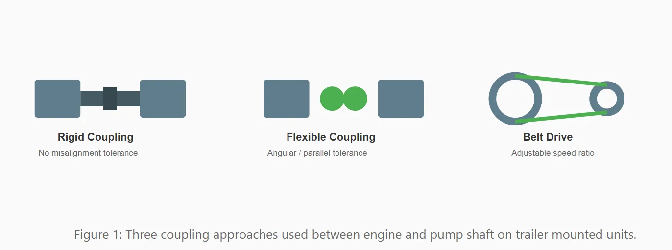
The coupling transmits torque from engine to pump shaft, and the design choice here governs both vibration behavior and how forgiving the system is of imperfect alignment during trailer transport and setup — a condition mobile pump units face far more often than stationary installations. A rigid coupling transmits torque with essentially no compliance, which demands precise shaft alignment and transmits vibration and shock loads directly between engine and pump — rarely used on mobile trailer units for this reason. A flexible coupling — jaw-type (elastomer spider between two hubs), disc-type (thin metal discs accommodating misalignment through flexing), or grid-type (a flexible steel grid) — tolerates a defined range of angular and parallel misalignment while damping torsional vibration, and is the standard choice on most trailer mounted diesel pump units for exactly that reason: trailer-mounted equipment is repeatedly repositioned and rarely re-aligned to stationary-installation tolerances between deployments.
Belt drive is the third option, and it decouples engine RPM from impeller RPM entirely through pulley ratio, which allows a pump curve to be tuned to a specific duty point using a fixed-speed engine rather than requiring a variable-speed governor. The trade-off is an added wear component — belt tension, glazing, and slip are a maintenance item that direct-coupled systems don’t have — and a small but real transmission efficiency loss compared to direct coupling.
| Coupling Type | Misalignment Tolerance | Vibration Damping | Maintenance |
|---|---|---|---|
| Rigid | Minimal | None | Low, but demands precise setup |
| Flexible (jaw/disc/grid) | Moderate angular & parallel | Good | Periodic element replacement |
| Belt drive | N/A (separate shafts) | Moderate | Belt tension checks, periodic replacement |
Pump End: Casing and Impeller Metallurgy
Casing and impeller material selection is driven by what’s actually in the water, not by a single default material used across every application. Ductile (cast) iron, typically to ASTM A536 grade specifications, is the standard choice for clean-to-moderate-solids dewatering work — cost-effective and adequately durable when abrasive content is low. Duplex stainless steel castings, referenced under standards such as ASTM A890, offer meaningfully better corrosion resistance and are the more appropriate choice in brackish, chemically aggressive, or corrosive water conditions where plain iron would degrade faster than the rest of the unit’s service life would justify. For water carrying heavy sediment or slurry loads, high-chromium white iron alloys (commonly 25–28% chromium content, referenced under ASTM A532 for abrasion-resistant white cast irons) are the material of choice specifically for their resistance to abrasive wear — a topic covered in more depth in our dedicated guide on wear-resistant pump metallurgy for high-sediment applications.
Impeller geometry is a separate design axis from material, and the two are chosen together based on water condition. A closed impeller — shrouded on both front and back sides — delivers the highest hydraulic efficiency and is the standard choice for clean water with minimal solids. A semi-open impeller, shrouded on one side only, sacrifices some efficiency but tolerates a moderate solids load and allows front clearance to be adjusted as the impeller face wears, extending service life before replacement is needed. A fully open or vortex-style impeller, with no shroud at all, handles the highest solids and stringy debris content — including the muddy or sediment-laden water routinely encountered in construction dewatering and flood response — at the cost of the lowest hydraulic efficiency of the three designs.
| Material | Reference Standard | Best Suited To | Relative Cost |
|---|---|---|---|
| Ductile (cast) iron | ASTM A536 | Clean water, low-to-moderate solids | Lowest |
| Duplex stainless steel | ASTM A890 | Corrosive, brackish, or chemically aggressive water | Moderate–high |
| High-chromium white iron | ASTM A532 | High-sediment, slurry, and abrasive service | High |
Sealing System
The shaft seal is where the rotating shaft passes through the stationary casing, and it’s a common failure point precisely because it sits at the intersection of a moving part, pumped fluid, and abrasive content — whatever the water is carrying. A mechanical seal uses two flat, precision-lapped faces (commonly a carbon face running against a ceramic or silicon carbide face) held together under spring pressure, providing a low-leakage seal with minimal ongoing adjustment. Silicon carbide face combinations are the standard upgrade for abrasive service, since they resist the face wear that softer carbon-ceramic pairings suffer when fine sediment migrates into the seal interface. A packing gland — braided packing rings compressed around the shaft — is the older, mechanically simpler alternative; it tolerates a wider range of abrasive conditions than a poorly matched mechanical seal, but requires a controlled drip of leakage for lubrication and cooling of the packing material, along with periodic manual adjustment as the packing wears and compresses.
Seal failure modes differ meaningfully between the two designs. Mechanical seals typically fail through face wear from abrasive intrusion, thermal cracking if run dry even briefly, or spring fatigue over extended service. Packing glands fail more gradually and predictably through progressive wear and require routine tightening, but a neglected packing gland — over-tightened to stop a leak rather than repacked — will generate heat and score the shaft sleeve, turning a simple maintenance item into a more expensive shaft repair.
| Seal Type | Leakage Control | Abrasive Tolerance | Common Failure Mode |
|---|---|---|---|
| Mechanical seal (carbon/ceramic) | Near-zero leakage | Low–moderate | Face wear from sediment intrusion |
| Mechanical seal (silicon carbide) | Near-zero leakage | Moderate–high | Thermal cracking if run dry |
| Packing gland | Controlled drip required | Moderate–high | Shaft sleeve scoring if over-tightened |
Chassis and Structural Frame
The trailer frame carries the engine, pump end, fuel tank, and control panel as a single towed structure, and its construction determines both towing stability and long-term corrosion resistance in a way that rarely shows up in a spec comparison. Frame corrosion protection generally falls into two categories: hot-dip galvanizing, where the steel is fully immersed in molten zinc, provides both a barrier coating and a degree of sacrificial (cathodic) protection at welds, cut edges, and minor coating damage, since the zinc corrodes preferentially to the steel beneath it; powder coating or paint provides barrier protection only — effective while the coating is intact, but offering no ongoing protection once it’s chipped or scratched, which is a routine occurrence on equipment repeatedly loaded, towed, and repositioned on active job sites.
Axle rating and weight distribution govern towing stability independent of frame material. The axle’s rated capacity needs headroom above the fully loaded trailer weight — engine, pump end, full fuel tank, and frame combined — and that load needs to be positioned so that tongue weight (the downward force the trailer places on the tow vehicle’s hitch) falls within the generally accepted target range of roughly 10–15% of gross trailer weight. A trailer loaded too far forward of the axle overloads the tow vehicle’s hitch and rear axle; loaded too far aft, it produces the sway-prone handling characteristic of an under-tongue-weighted trailer at highway speed. Suspension type — leaf spring versus torsion axle — is the final variable, affecting both ride quality (protecting the pump end and engine mounts from repeated road shock during transport) and maintenance requirements over the trailer’s service life.
Fuel and Lubrication Systems
Fuel tank construction on a diesel-driven trailer mounted pump increasingly follows a double-wall design — an inner tank holding fuel and an outer containment shell separated by an interstitial space that both provides secondary containment in the event of an inner tank leak and allows that leak to be detected before fuel reaches the ground. This construction is closely tied to environmental compliance requirements for fuel storage on mobile equipment, a subject covered separately in our SPCC compliance guide for trailer-mounted fuel systems.
Filtration staging matters as much as tank construction. A properly specified fuel system runs fuel through a primary fuel-water separator — removing free water and coarse contamination before it reaches the engine’s finer secondary filter — protecting injectors from both water intrusion and particulate damage. This same filtration stage is the first line of defense against the cold-weather fuel gelling failure mode covered in our guide to winterizing trailer mounted pumps, since a fuel-water separator that isn’t drained or maintained becomes a collection point for the water that accelerates wax crystallization at low temperatures.
On the lubrication side, the pump end’s bearing frame is typically either grease-lubricated (simpler, requiring periodic re-greasing at defined intervals) or oil-bath lubricated (a sealed reservoir providing more consistent lubrication film but requiring oil level monitoring and periodic oil changes). Engine lubrication follows standard diesel service intervals but is worth cross-checking against the engine’s rated duty class discussed earlier — an engine running at continuous heavy load needs oil analysis and change intervals scaled to that duty factor, not the standard interval printed for light-duty use.
System Integration: Why Component Mismatches Cause Field Failures
None of these subsystems perform in isolation, and a surprising share of field failures trace back to a mismatch between components that were each, individually, reasonable choices. A high-chromium abrasion-resistant casing paired with a standard carbon-ceramic mechanical seal loses much of its wear-resistance advantage, because sediment that degrades the seal faces reaches the shaft regardless of how hard the casing itself is — the weakest link in the abrasion-resistance chain sets the effective service life, not the strongest one. An engine rated for prime duty coupled to a pump end and impeller sized for peak, intermittent flow will spend most of its life under-loaded relative to its design point, which for a diesel engine can itself cause problems — incomplete combustion, cylinder glazing, and DPF regeneration issues associated with sustained light-load operation. A galvanized, corrosion-resistant frame built on an axle rated with little margin above the loaded trailer weight sacrifices the frame’s longevity advantage to a suspension or axle failure that has nothing to do with corrosion at all.
The practical takeaway is that reliability is a property of how the whole system was specified together, not a sum of best-in-class components chosen independently. A unit engineered as a coherent system — engine duty class matched to expected load factor, coupling matched to the mounting and vibration environment, casing and seal materials matched to each other as well as to the water condition, and chassis load rating matched with real margin above the as-built weight — will outperform a unit assembled from individually impressive components that were never designed to work as a set.
This same system-level approach is reflected in CANNASPRING’s ZBCY trailer-mounted dewatering pump, where hydraulic performance, solids handling, priming capability, sealing, and trailer mobility are specified as part of one mobile pumping package. See the ZBCY trailer-mounted dewatering pump for the corresponding specifications and configuration options.
Frequently Asked Questions
Q: If two trailer mounted pumps have the same flow and head rating, does that mean they’ll perform the same on site?
A: Not necessarily. Flow and head ratings are tested to standards like ISO 9906, which permit a defined tolerance band, and the rating says nothing about engine duty class, coupling type, casing and impeller metallurgy, seal design, or chassis construction — all of which affect real-world reliability and service cost independent of the hydraulic rating.
Q: What’s the practical difference between a mechanical seal and a packing gland?
A: A mechanical seal uses precision-lapped faces to achieve near-zero leakage with minimal routine adjustment, but is more sensitive to abrasive intrusion and dry-running damage. A packing gland is mechanically simpler and often more tolerant of abrasive conditions, but requires a controlled leakage drip for cooling and periodic manual tightening as the packing wears.
Q: Why does engine emissions tier matter for a mobile trailer pump?
A: The certification tier (such as EPA Tier 4 Final or EU Stage V) determines what aftertreatment hardware the engine carries — DPF, and in many cases SCR with DEF — which affects maintenance complexity, regeneration cycles, and in some cases whether the engine can legally be sold or operated in a given region.
Q: Is a flexible coupling always better than a direct rigid coupling on a trailer mounted pump?
A: For mobile equipment that’s repeatedly repositioned and re-set up on different sites, yes — a flexible coupling’s tolerance for minor misalignment and its vibration-damping characteristics suit the repeated setup cycles trailer-mounted units go through far better than a rigid coupling, which is more common on permanently installed, precisely aligned stationary pumps.
Q: Does a higher-grade casing material make the seal and coupling choice less important?
A: No — if anything it makes them more important. A premium abrasion-resistant casing and impeller only deliver their expected service life if the seal keeps abrasive content away from the shaft and the coupling keeps vibration and misalignment from accelerating wear elsewhere in the drivetrain. A weak link in any one subsystem limits the effective service life of the whole unit.
A Note on Relevant Engineering Standards
The design principles discussed in this article aren’t arbitrary manufacturer choices — most trace back to published engineering standards that define acceptable design and testing practice for centrifugal pumps and their drive systems. Readers wanting to verify a supplier’s engineering claims against a documented reference may find the following useful:
ISO 9906 (Rotodynamic Pumps — Hydraulic Performance Acceptance Tests) defines the test grades — 1, 2, and 3B — and associated tolerance bands used to verify a pump’s flow, head, and power against its rated point. This standard is the direct source of the tolerance concept referenced at the top of this article: a compliant pump is not required to hit its rated point exactly, only within the tolerance defined by the test grade applied.
API 610 / ISO 13709 (Centrifugal Pumps for Petroleum, Petrochemical, and Natural Gas Industries) is the benchmark heavy-duty process pump standard. While written for stationary process service rather than mobile equipment, its casing, shaft, bearing, and seal design provisions are widely referenced across the pump industry as a quality benchmark even where full compliance isn’t the applicable requirement.
ANSI/HI 1.3 and ANSI/HI 9.6.3 (Hydraulic Institute standards for rotodynamic centrifugal pump design and application, and for NPSH margin, respectively) provide the design and application conventions referenced in the pump curve and suction condition discussion elsewhere on this site.
ASTM A536, A890, and A532 define the material grades referenced in the casing and impeller metallurgy section above — ductile iron, cast duplex stainless steel, and abrasion-resistant white cast iron respectively — and are the standard reference point for verifying a supplier’s material claims against a recognized specification rather than a proprietary description.
SAE J1349 defines net engine power rating procedure and correction factors, which is the relevant reference when comparing horsepower or kilowatt figures quoted by different engine manufacturers, since gross and net rating methods can otherwise produce numbers that aren’t directly comparable.
If you’re comparing spec sheets from different suppliers and want help verifying what’s actually behind the numbers — engine duty class, coupling type, casing metallurgy, or seal design — contact the CannaSpring engineering support team with the spec sheets in question and your intended water conditions and duty cycle.